Auxiliary Outputs 4 & 5 (LectroCount Remote Display)
Auxiliary outputs 4 & 5 are typically used for the LectroCount Remote Display, but they can also be used for other types of displays. Signals from these outputs duplicate the volume data sent to the LCR 600 display.
Refer to the LectroCount remote display manual for complete installation instructions.
Follow these steps to wire an external display to the LCR 600:
1.Attach cable glands and/or conduit connectors to the display and the LCR 600 port(s).
2.Thread the wires through a piece of weatherproof conduit cut-to-length from the display port to a LCR 600 port
3.Pull the wires through the ports and tighten the connectors.
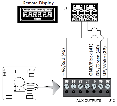
4.Connect the four display terminals to four terminals on the J18 terminal block of the LCR 600 CPU board.
•Remote display terminal 20 to LCR 600 terminal 45
•Remote display terminal 21 to LCR 600 terminal 39
•Remote display terminal 22 to LCR 600 terminal 40
•Remote display terminal 23 to LCR 600 terminal 41
Other Auxiliary Outputs
The LCR 600 provides three open-drain transistor auxiliary outputs for different external devices–such as pump controls and additive injectors. The schematic to the right identifies the J13 terminals where the auxiliary outputs can be connected to the LCR 600.

Disconnect Power |
Disconnect the power before working on the CPU board. |
Auxiliary Output 1 (Out 1)
This signal has four output settings: Off, On, On During Delivery, and Monitor Flowrate.
Auxiliary Output 2 (Out 2)
This signal has three output settings: Off, On, On During Delivery, and Flow Direction.
Pulse Output (Out 3)
This output represents the gross delivery quantity for uncompensated deliveries or the net delivery quantity (for compensated deliveries). This output is a real time 50/50 duty cycle representing the least significant digit of the LCR 600 totalizers.
Auxiliary Output Settings |
To select the Auxiliary Output settings, refer to the LectroCount LCR 600 Setup and Operation manual. |