WIRING CONDUIT SYSTEM
When wiring the POD, the wires must enter through the POD’s conduit hub. For explosion-proof rated systems (Class I, Div 1), the wiring must be in explosion-proof rated rigid conduit, or–for high vibration installations–explosion-proof rated braided flexible conduit. The conduit must be engaged five (5) full threads into the female hub on the POD to meet explosion proof requirements.
When installing in a Division 2 location, use either rigid conduit, flexible conduit, or no conduit. When no conduit is used, the instrument cable must be brought into the POD conduit hub using a cable gland to seal the wiring to maintain the Enclosure NEMA 4X rating. Regardless of the type of connection used, thread sealant should be applied to prevent moisture from getting into the POD electrical housing.
 |
OBSERVE NATIONAL & LOCAL CODESNorth America – Installations must be in full accordance with the National Electrical Code (US) or the Canadian Electrical Code respectively to maintain the hazardous location ratings on the product.
Outside of North America – Installations must be in full accordance with EN 60079-14 to maintain the hazardous location ratings on the product. Use Ex d certified cable glands only. For ambient temperatures above 70ºC, use field wiring rated 20ºC above the maximum ambient temperature. |
WIRING CABLE
Multi-wire cable with an overall shield is recommended for POD wiring. If individual wires are used, they must be in a flexible metal conduit and must not be run with any other cables or wires. Use individual wires between 16 and 20 AWG or shielded cable no less than 22 AWG. Cable runs up to 5,000 ft (1,524 m) are possible, however cable runs over 1,000 ft (304.8 m) should use lower AWG wire to reduce the IR voltage drop and the inter-wire capacitance. In addition, long runs may require a lower value pull-up resistor (due to the additional cable capacitance that the pulser must drive). Cable that has a metalized foil plastic shield with a drain wire is recommended over cable with woven shields because it is easier to terminate the drain wire type cable.
TERMINAL BLOCK
Removing the cover of the POD will expose a 4–position terminal block for connection to an electrical system. The terminal block can be unplugged from the board for ease of wiring. Pull it straight up to remove.
The terminal block screws require a straight blade screwdriver with a tip less than ⅛" wide. Before inserting wires into the terminal block, strip ¼" of insulation off each wire. Turn each terminal screw counterclockwise a few turns to make sure that the wiring slot is fully open to accept wire. Insert the stripped end of the wire and tighten the terminal block screw.
Plug the terminal block back into the board if it was removed. Be sure it is properly oriented with the four pins.
WIRING CONFIGURATIONS
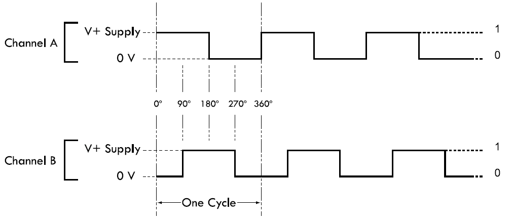
The wiring configuration used depends on the system needs. Check the input requirements of electronic controls to determine single channel or quadrature output. The POD can be wired using only one of the two channels (Channel A or B) if the flowmeter has flow in only one direction. To detect both forward and reverse flow, both channels (which are in quadrature to each other) must be used. Channel A will lead Channel B by 90º in one flow direction and Channel B will lead Channel A in the reverse direction. Quadrature is required in most Weights & Measures approved installations.
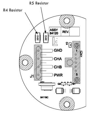
CONVERSION TO OPEN DRAIN OUTPUT
As supplied by the factory, the POD has a 2.2 KΩ pull-up resistor to the positive power supply on each output transistor. The unit can be modified in the field to provide true Open Drain (Open Collector) outputs if desired.
Follow these steps to modify the POD to Open Drain outputs:
1.Turn off power to the unit and remove the cover by turning it counterclockwise. 2.Loosen the three circuit board mounting screws using a Philips screwdriver. Remove the entire circuit board assembly from the POD housing. 3.With a small tip soldering iron, remove the R4 and R5 resistors. 4.Carefully, apply heat to one pad of the resistor. 5.When the solder melts, push the resistor off the circuit board with the tip of the soldering iron. 6.Remove the second resistor using the same method. 7.Reassemble the unit. |
|
SIGNAL OUTPUT
The diagram below shows the voltage output for a clockwise rotation of the Pulse Output Device (POD) with Channel A leading Channel B. For reverse flow applications (counterclockwise) Channel B leads Channel A.
NOTE: Quadrature channel voltage output is 90° out of phase with Channel B.